



Thin Wall CNC Machining: One Setup, No Deformation
Published on Thursday, 22. October 2026
Content Guide:Single-setup thin wall CNC machining for aluminum, stainless, and titanium parts. No stress relief, no secondary ops, walls under 1mm held to five-thousandths.
Thin wall aluminum parts are one of the places where Precision machining stops being about the machine and starts being about the process. Walls under 1mm move during cutting, and the usual answer — stress-relief treatment, a second setup, a finishing pass after re-clamping — adds time and still leaves you chasing the tolerance.
What we do instead is machine the part in a single setup, no stress relief, no secondary operations, and hold five-thousandths of an inch on the wall. The rest of this page explains how that works: the fixturing, the toolpath, and the cutting strategy behind it.
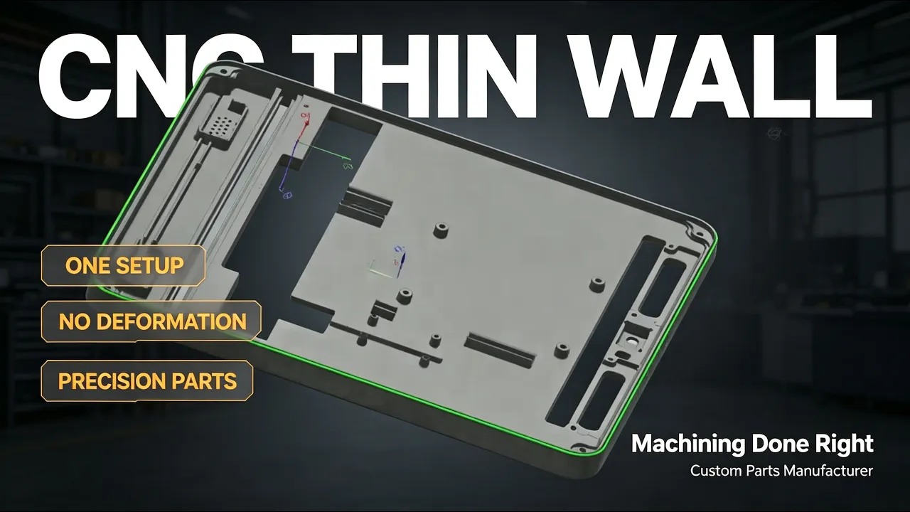
Thin wall aluminum housing finished in a single setup, wall thickness under 1mm
Most thin wall problems are not caused by the finishing pass. They are set up in roughing. When you remove material from one side of a wall, the residual stress in the stock redistributes, and the wall deflects. Clamp it again for finishing and you add a second distortion on top of the first. By the time the part comes off the table, the wall has moved in a direction you did not cut for.
That is why adding a stress-relief step or a second setup often does not fix the problem — it just moves the distortion to a different stage. The fix has to happen inside the single setup, in how the wall is supported and how the load comes off it.
The fixture has to hold the wall rigid while it is still attached to the stock, and then release it without springing. In practice this means two things: support the wall from the back side wherever the geometry allows, and keep clamping force off the wall itself.
For housings and enclosures, we usually leave a sacrificial web connecting the wall to the base until the last operation. The wall is machined while supported, then the web is cut in a sequence that releases the part gradually instead of all at once. Custom fixtures are planned per part — there is no universal clamp that works for every thin wall geometry.
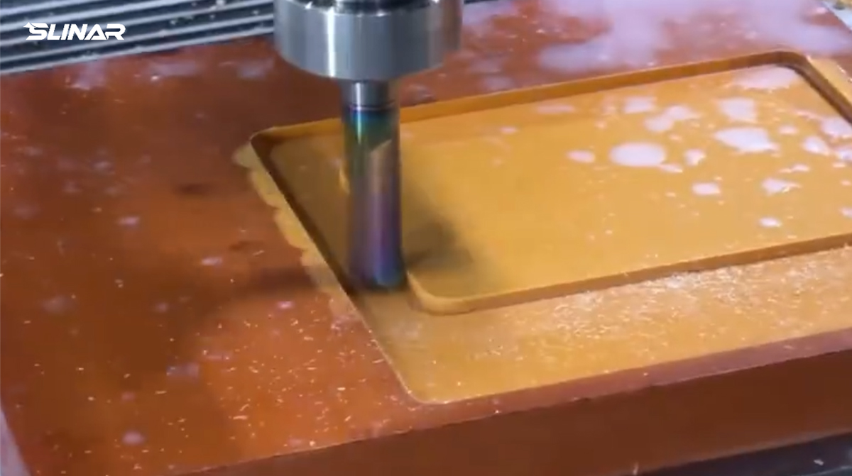
Custom fixture supporting the wall from the back side during roughing and finishing
For walls under 1mm, the radial cutting force is what pushes the wall away from the cutter. Reducing that force matters more than reducing the spindle load.
We use small-diameter end mills with a high helix and a sharp edge, and keep the radial depth of cut low while increasing the axial depth. This shifts the cutting load from the wall’s weak direction into the tool’s stiff direction. Finishing passes are kept constant in width — varying the cut width mid-wall is one of the fastest ways to introduce a wave that shows up in inspection.
Cutting parameters are set per material and wall thickness. Aluminum is forgiving compared to stainless or titanium, but the same principle applies: low radial load, constant engagement, and no sudden change in direction along the wall.
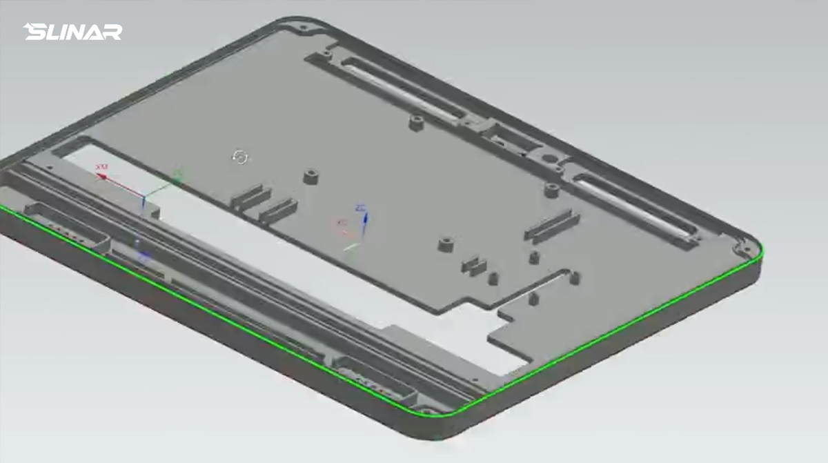
Toolpath with constant radial engagement along a sub-1mm wall
The same single-setup approach is used across 3-axis, 4-axis, and 5-axis work, for thin wall aluminum, stainless steel, and titanium parts. Typical parts are housings, enclosures, and complex structural components where wall thickness and tolerance both matter.
If you have a thin wall part you are not sure is machinable, send the drawing and the wall thickness. We will tell you whether the single-setup route applies, or whether the geometry needs a different plan. Feasibility assessment and production quotes are returned within 24 hours.
Previous:8 Gear Machining Methods Explained – A Complete Guide
Next:No More/End