



PEEK Milling: Tool Geometry for Burr & Melt Control
Published on Thursday, 15. October 2026
Content Guide:Rake angle, clearance, and DLC coating decide PEEK surface quality. Practical tool geometry guidance for aerospace and medical milling.
The Philosophy of PEEK machining Tools: How to Optimize Tool Geometry to Resolve Common Surface Quality Issues
Anyone who hAs Machined PEEK for aerospace or medical parts knows the pattern. The material has the strength, the temperature resistance, the chemical stability. Then it hits a milling machine and turns on you. Its toughness sits somewhere between plastic and metal, and its thermal conductivity is poor, so cutting heat has nowhere to go and builds up right at the edge. The result: burrs at the exit, a whitened side wall, occasionally a ring of melted residue stuck to the cutter, and dimensions that drift.
The first instinct for most process engineers is to adjust spindle speed and feed. That is not useless, but if the tool geometry is wrong to begin with, parameter tuning is just arguing with a bad premise. What we found after a few PEEK jobs is that most surface quality problems trace back to the cutter, not the speed and feed table.
What is actually happening: PEEK does not shear, it gets pushed
Understand the failure mechanism before talking about tool design.
When milling steel, most of the cutting heat leaves with the chip, and the edge shears the material cleanly. PEEK is different. Its low thermal conductivity concentrates heat in a small zone at the edge and workpiece contact. The material softens first, then gets pushed along by the edge instead of separating cleanly. After it cools, it shrinks, and the dimension moves.
The bigger problem is elastic recovery. As the edge passes, the material springs back just as it leaves the cutting zone and rubs against the flank face. That rub extrudes and friction-burns the surface layer, leaving the white, degraded skin. Exit burrs come from the same mechanism: the material is not left uncut, it is cut and then pulled back and torn.
So the design logic comes down to one sentence: get the material to shear cleanly at low temperature, not to be pushed. That breaks into three things — a sharp edge, enough clearance, and fast chip evacuation.
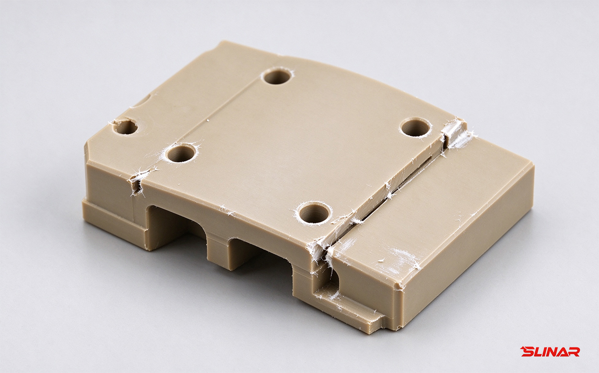
Typical burr, whitening, and melt residue on a PEEK milled surface
Rake angle and clearance angle: both have to be generous
The rake angle controls cutting force and heat. For PEEK, go positive and go large — 10° to 20°. This lets the edge slice the material rather than pry it. Cutting force drops, heat generation drops, and melting and burring are suppressed at the source.
The clearance angle handles the friction between the flank face and the machined surface. Because PEEK springs back, the flank needs enough room to avoid rubbing. In practice, 12° to 15° works. Go too small and you get the whitened layer and the dimensional drift that comes with it. The two angles together are what give you a genuinely sharp edge, not just a geometrically sharp one.
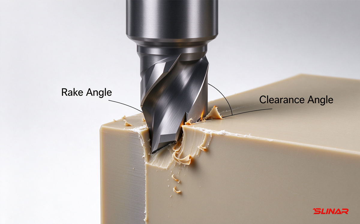
Large positive rake and large clearance are the baseline for PEEK tooling
Edge honing: the part most people skip
A very sharp edge is also a fragile edge. An untreated edge has microscopic chips and imperfections along the cutting line. In PEEK, those defects wear fast, and once the edge starts to go, surface quality drops with it.
Honing at the micron level — typically 0.01 to 0.03 mm — is not about dulling the edge. It removes the microscopic defects and leaves a smooth, uniform micro-radius that is stronger than the raw edge while still cutting. In our experience, this is the difference between a tool that holds its finish for a full batch and one that starts pulling material after twenty minutes.
Coating: the goal is friction reduction, not wear resistance
In steel machining, coating is mostly about wear resistance. In PEEK, it is about friction. DLC (diamond-like carbon) is close to ideal here. Its coefficient of friction is very low, which keeps cutting heat down and stops material from sticking to the edge. For general precision work at ±0.05 mm with a good surface finish requirement, a DLC-coated tool is the straightforward choice.
If DLC is not available, a high-quality uncoated carbide is the next best option. What you want to avoid is TiAlN and similar conventional coatings. Their chemical affinity with PEEK tends to make chip adhesion worse, not better, and the heat buildup follows.
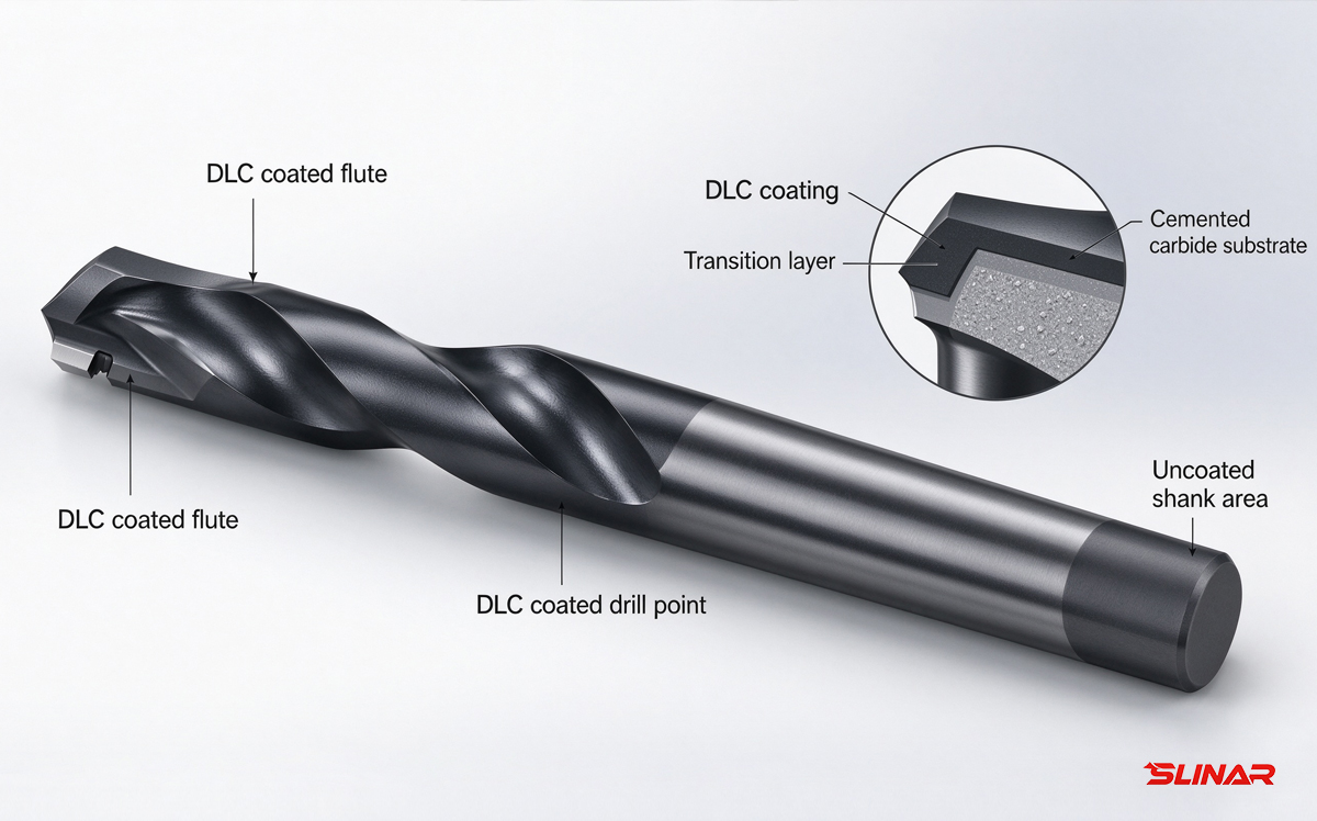
DLC coating provides a low-friction barrier against PEEK adhesion
Chip flutes: where the heat actually leaves
Spacious, polished flutes matter more in PEEK than in most materials. PEEK produces long, continuous chips. If the flute cannot move them out fast, they get recut, and the heat spikes. A polished flute wall lowers flow resistance, which means heat leaves with the chip instead of soaking into the workpiece.
Two or three flutes is usually the right balance for PEEK. Fewer flutes give you more chip room; more flutes give you rigidity but choke the evacuation. For roughing and semi-finishing, two or three flutes is where we land most of the time.
Tool selection by operation
Roughing: Two- or three-flute flat end mills, large rake angle, high helix (30°–45°), DLC coating. The priority is moving chips, not surface finish.
Side wall finishing: Two- or three-flute square shoulder or long-edge mills. Edge sharpness and runout accuracy are what determine perpendicularity and wall finish here. Check runout before blaming the parameters.
Grooving and slotting: Two-flute slotting cutters. Make the slot slightly wider than the tool and put an end relief on the cutter to cut bottom friction.
Contour and 3D surfaces: Ball nose end mills. The rake angle design and the polish on the ball section matter most. DLC helps reduce drag marks on contoured surfaces.
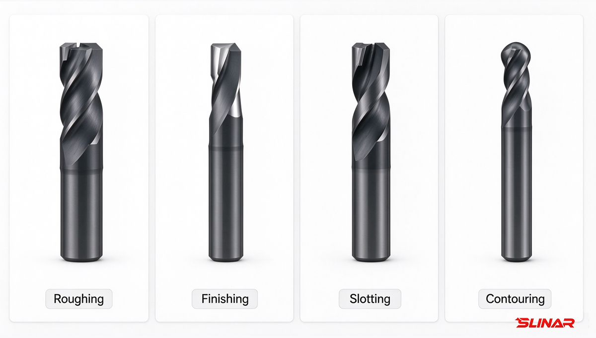
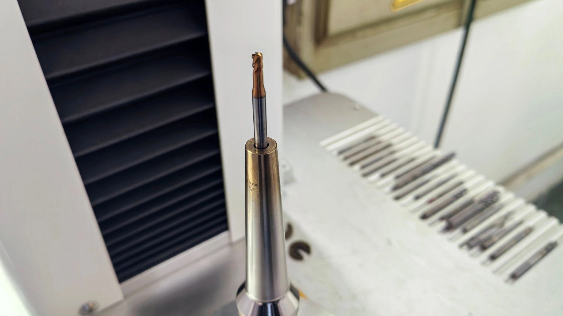
PEEK-specific tooling for roughing, finishing, slotting, and contouring
What this comes down to
machining PEEK is a balancing act between a rigid tool and a sharp one. The cutters that work are the ones where the geometry has been thought through: large rake and clearance for clean shearing, micron-level honing for edge life, DLC or a good uncoated finish for low friction, and open, polished flutes for chip evacuation. The point of all of it is to push the material toward shearing instead of extruding, so burrs, whitening, melting, and dimensional drift do not show up in the first place.
For ±0.05 mm work, stop treating the cutter as a consumable you grab off the shelf. Treat it as a process variable. Talking to a tool supplier who actually understands PEEK, and getting a series optimized for it, will usually get you further than another round of parameter adjustments after the fact.
Previous:Optimize 6061 Aluminum Milling: Parameters, Tools & Tips for Engineers
Next:No More/End